I have been working in sports analytics for 2 years now. I am mainly focusing on the computer vision side of things but saying “sports analytics” is a good way to make it sound more interesting. My goal is simple: extract as much information as possible from sports event video feeds and ensure the data is high-quality. In order to achieve this, I must be able to pinpoint the real world location of the objects observed in the video feed. In other words, map pixels in the video feed to real world coordinates. That mapping is what I refer to as homography. I have already written a post in the company blog about this. If you are interested in why it matters and what it can be used for, you can check it out here.
Lately, I’ve been inspired by the incredible projects people have been creating with the help of Copilot. This sparked my curiosity to explore firsthand the experience of coding with a heavy reliance on this tool. I’ve decided to challenge myself by attempting to write some JavaScript code. So, be kind and withhold judgement on any of the code you see. After all, I’m no JavaScript developer; I’m essentially in GPT-4’s hands here 😎.
The goal
The goal is straightforward: for any given American football NFL event video feed, I want to map the pixels in the video to their corresponding real-world coordinates. Essentially, I want to pinpoint the location of the ball, the players, the goal, etc. The simplest approach to tackle this problem consists of working at the frame level and figuring out how to match each image to a predefined pitch template.
When I joined StatsBomb, there was a similar and more advanced tool already developed. My goal here was just to be sure I could replicate the entire process from scratch and have a complete understanding of it. So I wanted to develop a simple web app that allows users to upload an image and then find the correspondence between that image and the pitch template. The pitch template is a basic image of the pitch, including lines and goalposts.
The result
Here’s the result for you to explore directly. There are just a few steps to follow:
- Upload image of a NFL game
- Select at least four points in the image and the pitch template. Be sure to select the same points in both images.
- Click on the “Compute homography” button to see the warped pitch template overlaid on the uploaded image.
Make sure to read the following sections for a deeper understanding of how it all works.
You can find all javascript code in this file.
Some extra details
Pitch template
The pitch template is a controlled image I use to model the real-world pitch. By mapping image objects to it, I can directly measure their distances and angles. This is crucial for extracting meaningful information later on, such as ball position, player location, and player speed.
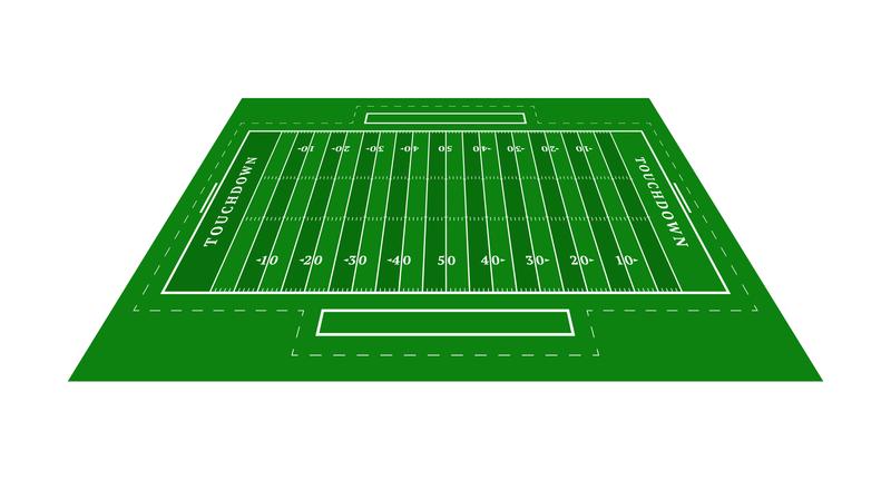
First, I must understand how the dimensions of an American football pitch are defined. This page is an excellent resource. It’s worth noting that I solely focused on NFL dimensions, as NCAA fields differ slightly.
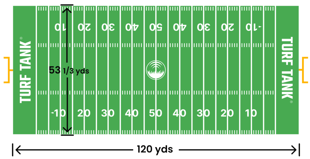
NFL Pitch dimensions obtained from https://turftank.com/us/academy/how-big-is-a-football-field/
I created a simple image with the same resolution as the NFL pitch, 120 x 53.3 px. This means one pixel in the image equals one yard in the real world. Next, I added end zones, hash marks, yard numbers, and all the necessary elements, each positioned accurately. I have to admit that although this task should be relatively simple and mechanical, it took me a while to achieve a decent result. Be sure to check the real code, but see below a small example that can help you realize the amount of handcrafting needed to create a good template:
    // Define the pitch dimensions and other constants
    const pitchHeight = 53 + 1/3;
    const pitchWidth = 120;
    const lineWidth = 2;
    const ctxTemplate = templateCanvas.getContext('2d');

    // Set size and color of template canvas
    ctxTemplate.strokeStyle = 'red';
    ctxTemplate.fillStyle = "black";
    ctxTemplate.fillRect(0, 0, templateCanvas.width, templateCanvas.height);

    // Translate to avoid cropping the sidelines
    ctxTemplate.lineWidth = lineWidth;
    ctxTemplate.translate(lineWidth, lineWidth);

    // Side lines
    addLine({ x: 0, y: 0 }, { x: 0, y: pitchHeight });
    addLine({ x: pitchWidth, y: 0 }, { x: pitchWidth, y: pitchHeight });

    // End lines
    addLine({ x: 0, y: 0 }, { x: pitchWidth, y: 0 });
    addLine({ x: 0, y: pitchHeight }, { x: pitchWidth, y: pitchHeight });
I repeated this process for all pitch elements, resulting in the image below:
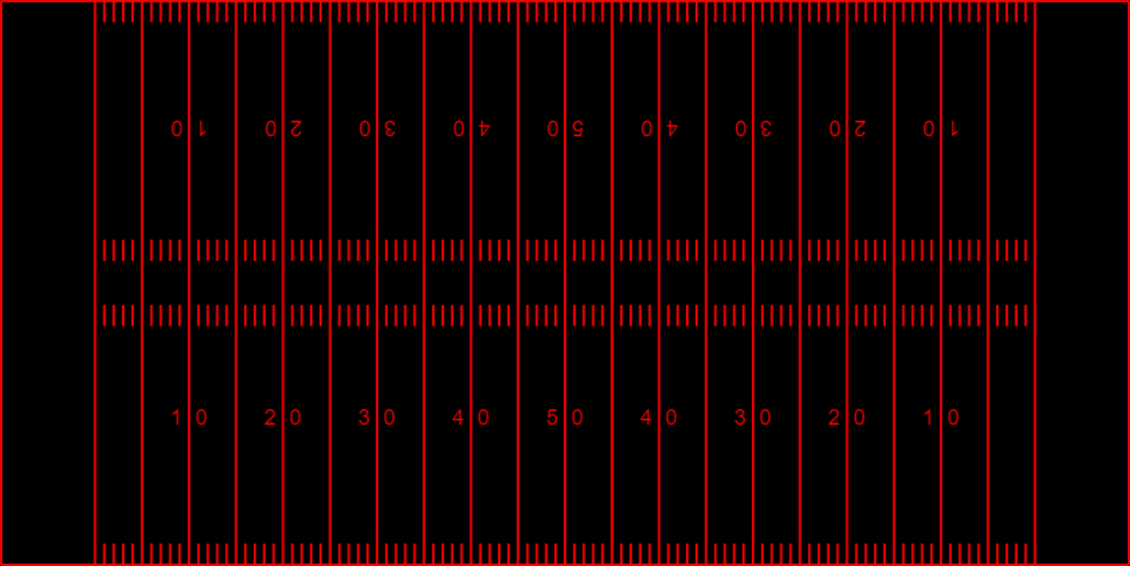
NFL resulting pitch template image
Bear in mind though that you are observing a scaled-up version of a 120 x 53.3 px image in the web app, adjusted to match your screen size.
Recovering the homography
Homography maps the pitch template to the uploaded image, allowing for corresponding points between the two. The theory behind this is extensive and beyond this post’s scope. To be fair, I can’t do better than what my colleague Iñaki Rabanillo has done in his own blog. So, I will just refer you to his post, be sure to check it out since it is a brilliant piece of work.
To sum it up, the problem we need to solve consists mostly of finding a homography transformation that is represented by a 3x3 matrix. This will allow us to go from pixel coordinates $p_i$ in the image to real world coordinates $p_t$ in the template image. To do so, we just need to carry out a matrix multiplication:
\[p_t = H \cdot p_i\]If you are now wondering how can you multiply a 3x3 matrix by a 2x1 vector, you are right. We need to add a 1 to the vector to make it a 3x1 vector. This is a common trick in computer vision and it is called homogeneous coordinates. It is a way to represent points in a way that makes it easier to perform transformations on them. Be sure to check Iñaki’s post for a deeper understanding of this.
The homography matrix $H$ is a 3x3 matrix that has 8 degrees of freedom. This means that we need at least 4 points in the real image and their corresponding pairs in the template image to solve for the homography. This is a simple problem to solve and there are a lot of libraries that can do it for you. I used OpenCV library although you could just create the system of equations and solve it using any linear algebra library (specially if you are used to work with Javascript more than me).
This is the code that retrieves the homography matrix from the list of points and applies it to the template image:
    function computeHomography() {
        // Check that both lists of points have the same size and that their size is at least 4
        if (pointsImage.length !== pointsTemplate.length || pointsImage.length < 4) {
            alert('Both lists of points must have the same size and contain at least 4 points');
            return;
        }

        // Convert points to cv.Mat format
        let imagePoints = cv.matFromArray(pointsImage.length, 1, cv.CV_32FC2, pointsImage.flatMap(point => [Math.round(point.x), Math.round(point.y)]));
        let templatePoints = cv.matFromArray(pointsTemplate.length, 1, cv.CV_32FC2, pointsTemplate.flatMap(point => [Math.round(point.x), Math.round(point.y)]));

        // Compute homography
        let homography = cv.findHomography(templatePoints, imagePoints);

        // Check if homography is none because of colinear points
        if (homography.empty())
        {
            alert("Could not found any homography for these sets of points. Be sure they are not colinear.");
            return;
        }

        // Warp the template image using the homography
        let warpedTemplate = new cv.Mat();
        cv.warpPerspective(templateImage, warpedTemplate, homography, sourceImage.size());

        // Add the warped template to the source image
        let resultWeighted = new cv.Mat();
        cv.addWeighted(sourceImage, 1, warpedTemplate, 0.5, 0, resultWeighted);
        cv.imshow('imageCanvas', resultWeighted);

        // Clean up memory
        imagePoints.delete();
        templatePoints.delete();
        warpedTemplate.delete();

        return homography;
    }
Projecting between image and template
Once we have the homography matrix, we can project any point in the image to the template (and viceversa). This just requires us to do a simple matrix multiplication. As it was mentioned before:
\[p_t = H \cdot p_i\]It is also possible to do the opposite, projecting a point in the template to the image:
\[p_i = H^{-1} \cdot p_t\]Quite simple, right?
Conclusion
I hope you enjoyed this post and the web app. I have been using python for a long time and seeing things coming to life in the browser feels like something new now. I also had time to revisit some of the theory behind the homography and I am always happy to do so. I hope you found it interesting and that you can use it as a starting point for your own projects. I am sure there are a lot of improvements that can be done to this code and I would love to hear your thoughts on it.
Any ideas for future posts or is there something you would like to comment? Please feel free to reach out via Twitter or Github